Having witnessed recent confusion and inaccuracies in a recent publication I thought a look back at current measurement, tools and process, its intended to provide some much needed clarity.
Our history, and the measurement of current goes all the way back to the dark days of off car ecu testing, using a network 500 terminal. It became very obvious that simulation of load did not fully and accurately test current path through various components, especially ignition and injector circuits.
.As a consequence we approached the electronics industry asking the question, how do we measure current in high speed intermittent switched circuits?

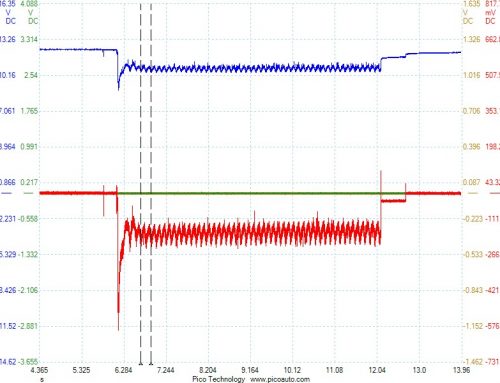
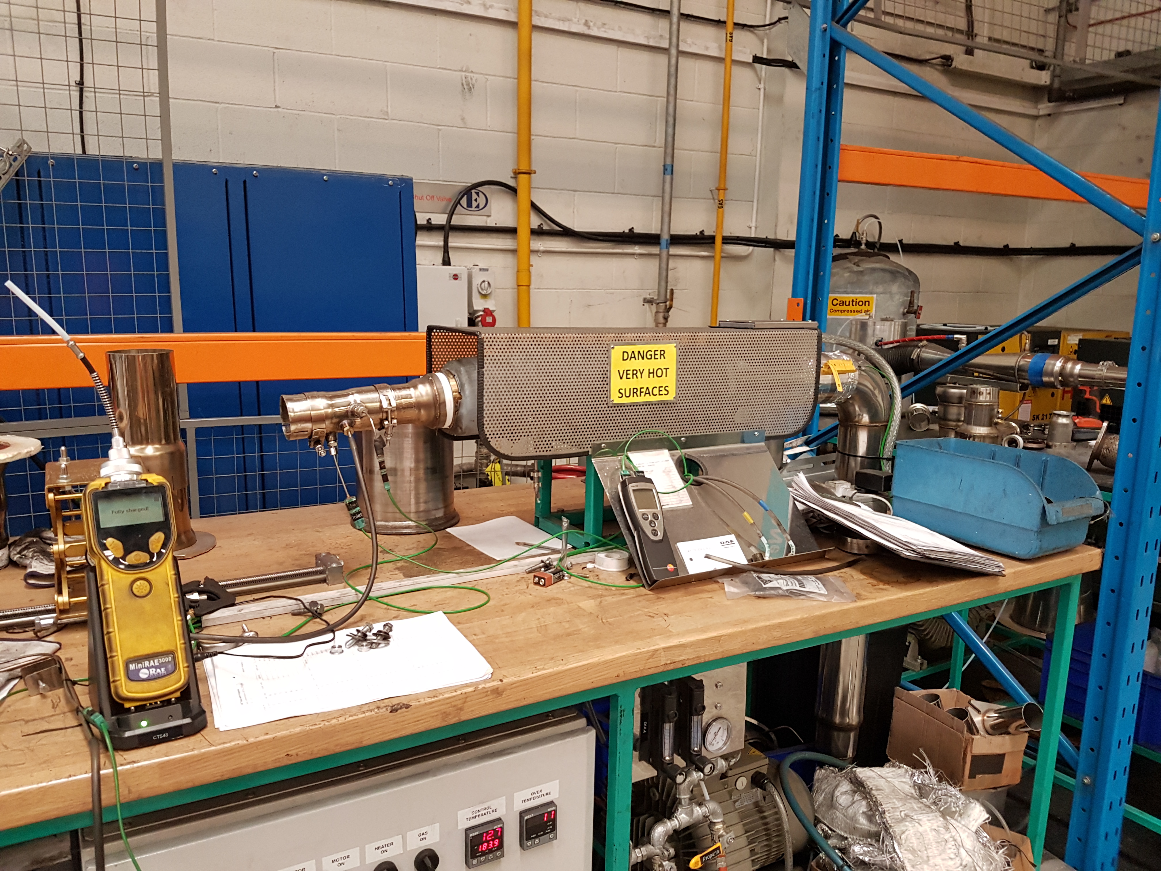
Pic shows a variable demand low pressure vw tfsi pump circuit under test.
Let’s begin with some absolute basics,
Voltage is electrical pressure, or potential difference. Voltage differential cannot exist without a complete circuit and load.
The unit of measurement is the volt.
Current is the measurement of flow, current cannot exist without a consumer, in a conventional ground on circuit when voltage falls an increase in current will start to occur at the same time . The unit of measurement is ampere.
The load in a circuit should only be consumed by the component, the unit of load is the watt.
It should therefore be possible to predict the response in a circuit by applying ohms law!
Voltage divided by amps x resistance, however in complex vehicle control circuits it’s not that straight forward. However the tools and process do not change.
Vehicle components vary in nature, they do however share one common fact, they apply a resistance in a circuit, and sometimesit’s so small or switched so quickly that it cannot be measured accurately without special high performance tools.
When load is applied in a circuit the voltage will change very quickly, however and this depends how the load is switched, the current takes longer to accumulate. This phenomenon depends on the available pressure, flow rate and load.
Most vehicle components discussed here fall into the category of inductors. Inductors are essentially coils, the nature of which apply considerable loads when introduced into a circuit.
They are usually switched, ground on, this can however be reversed. The onset of complex control motors in vehicle systems demands a more responsive means of switching whilst, reducing where possible the current through the pcm. This method is referred to as pulse width modulation PWM. By pulsing a circuit the duty cycle controls the current ramping. It also provides accurate response and feedback.
Components that require ultra-rapidresponse, cr injectors for example employ capacitors to multiply the voltage from a nominal 15v to approx. 120v. This has the added effect of increasing the rise time of current flow.
So the poor old ohms law looks a little vague!
So what isthe critical criteria when evaluating actuators and what tools actually work, and where can I get them?
Correct Current flow is very important however its only one off 3 critical components.
1\ current flow
2\ rise time
3\ induction
Rise time relates to the resistive value and the available pressure, ever tried to get a golf ball down a drinking straw! The unit of induction is the henry. This applies especially when testing the rate of response within an injector, againstthe control on signal.
It takes into account voltage, currentflow, current rise time, speed of current interruption, and the electromagnetic field effect the pintle movement has to the current path, temperature also has a part to play.
One thing is for certain, as I recently observed to the contrary in a technical journal, the voltage and current flow must share a common response.
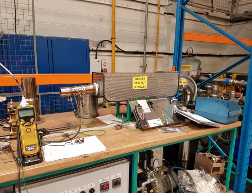
So how do we measure current and why current first. Current flow is equal throughout the entire circuit, so the opportunity is much easier. The control fuse or power relay for example. Using an inductive current clamp (it’s actually a hall device) ensures a non-intrusive means of measurement. The sensitivity and rise time of the clamp is vital, more lately.
It not only provides measurement of flow but the effectiveness of the current interruption, this of course is imperative for good induction. This is the responsibility of the power transistor within the pcm, or ignition coil as with the latest direct ignition systems.
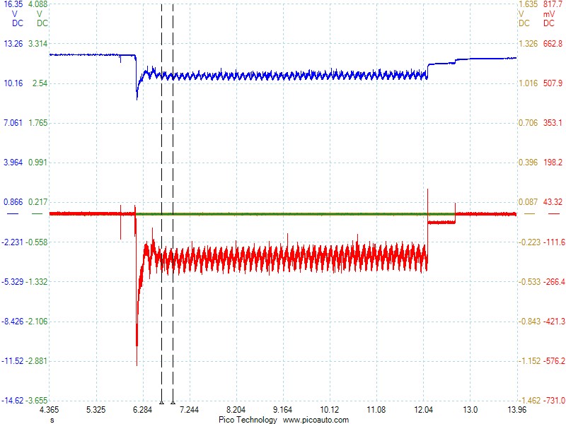
The tool of choice is of course my pico and a range of current clamps, the critical observation is profile or shape. You won’t find this data in any books it’s taken me over 30 years to find the confidence and knowledge in current testing.
Let’s examine some examples- ![]()
![]()
![]()
![]()
![]()


Leave A Comment